Infill in 3D Printing: Definition, Main Parts, and Different Types
Learn about the importance of infill in 3D printing design and the different types of infill patterns.

3D printing infill refers to the internal structure of a 3D printed part. This internal structure can be produced using many different shapes. The purpose of infill is to optimize part weight, strength, and printing time. Many different infill patterns exist. These standard designs can be selected in the 3D slicing software menu used to prepare parts for printing.
This article will define 3D printing infill, discuss how to select the correct infill pattern and density, and describe the various infill patterns.
What Is Infill in 3D Printing?
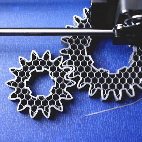
“Infill” in 3D printing refers to the internal patterns found inside most 3D printed parts. Parts made by some manufacturing processes, like injection molding, must be made either completely solid or completely hollow. 3D printed parts, on the other hand, can be made with a variety of structural patterns that partially fill the space inside the outer printed walls. Almost all 3D printing technologies require infill. This is the case because printing objects in a solid material are too costly and time-consuming. For more information, see our guide on Everything You Need to Know About 3D Printing.
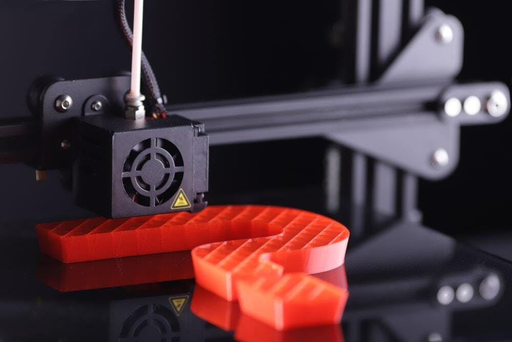
Figure 1 below shows the infill of a 3D printed part.
3D printer manufacturing big question mark.
Image Credit: Shutterstock.com/R_Boe
What Is the Purpose of Infill in 3D Printing?
The purpose of Infill in 3D printing is to save both printing time and material by creating a lattice structure inside of a 3D printed part. Printing fully dense parts is often unnecessary and is just a waste of material. The infill can be strategically placed to provide strength where in-service loads on the part are the highest. The greater the percentage of infill, the higher the density of the part.
What Are the Main Parts of Infill in 3D Printing?
A typical 3D printed part will have an outer shell with a predefined thickness. The infill structure is completely enclosed by this outer shell and is not visible when the part print is complete. The infill will be evenly distributed throughout the part. 3D printing infill is normally printed at higher speeds than the outer shell to save time. The infill print lattice is also not as thick as the shell. The many different infill patterns each have their own advantages and disadvantages.
What Are the Different Types of Infill in 3D Printing?
There are many different types of 3D printer infill. All achieve the same purpose of reducing print time and material usage. Below are some of the 3D printing infill patterns in use today:
1. Line: Line infill consists of multiple parallel lines per layer. Each layer crosses over the previous one at a 90-degree angle. Unlike other patterns, the lines don’t cross over each other on the same layer. This strengthens the part in two dimensions. Line infill is marginally quicker than grid and triangular patterns. Figure 2 is an example of line infill:
Line infill.
Image Credit: Xometry.com
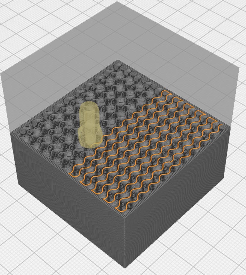
2. Gyroid: The gyroid 3D printing infill pattern creates alternating wavy lines or curves. This infill pattern takes longer to print than the others. However, the unique gyroid internal structure allows for almost isotropic mechanical properties. Prints are still weaker on the z-axis but this pattern improves the x and y-axis shear strength. The gyroid pattern works well with flexible materials. Figure 3 is an example of a gyroid infill pattern:
Gyroid infill.
Image Credit: Xometry.com
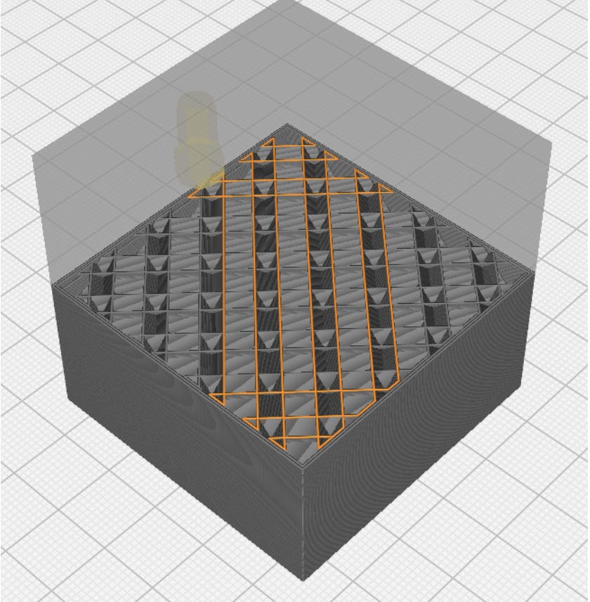
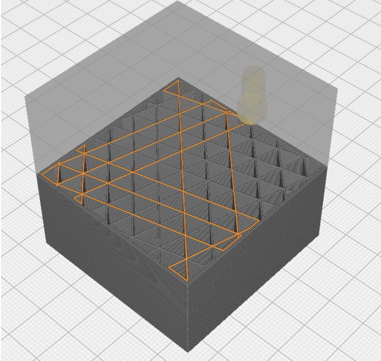
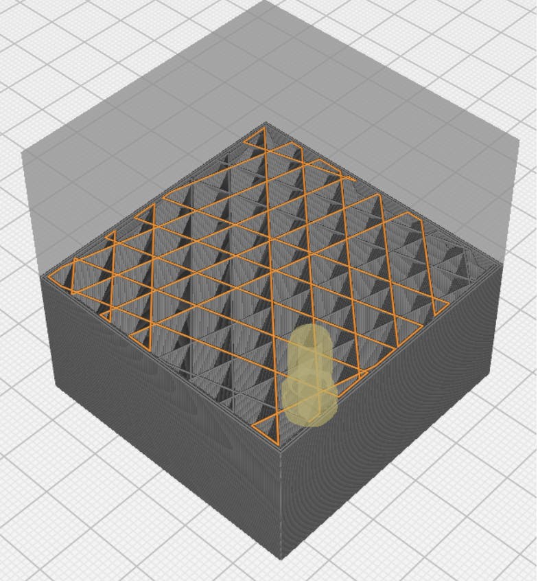
3. Octet: The octet 3D printing infill pattern creates tetrahedral (pyramid-like) volumes inside the part. It is best for parts with large horizontal surfaces. Smaller gaps between the infill walls are possible due to the tapering nature of the pyramid-like volumes. This allows for shorter span distances between infill walls and a lesser chance for the material to sag. Improved top surfaces can therefore be achieved without having to increase the infill density. Figure 4 is an example of an octet infill pattern:
Octlet infill.
Image Credit: Xometry.com
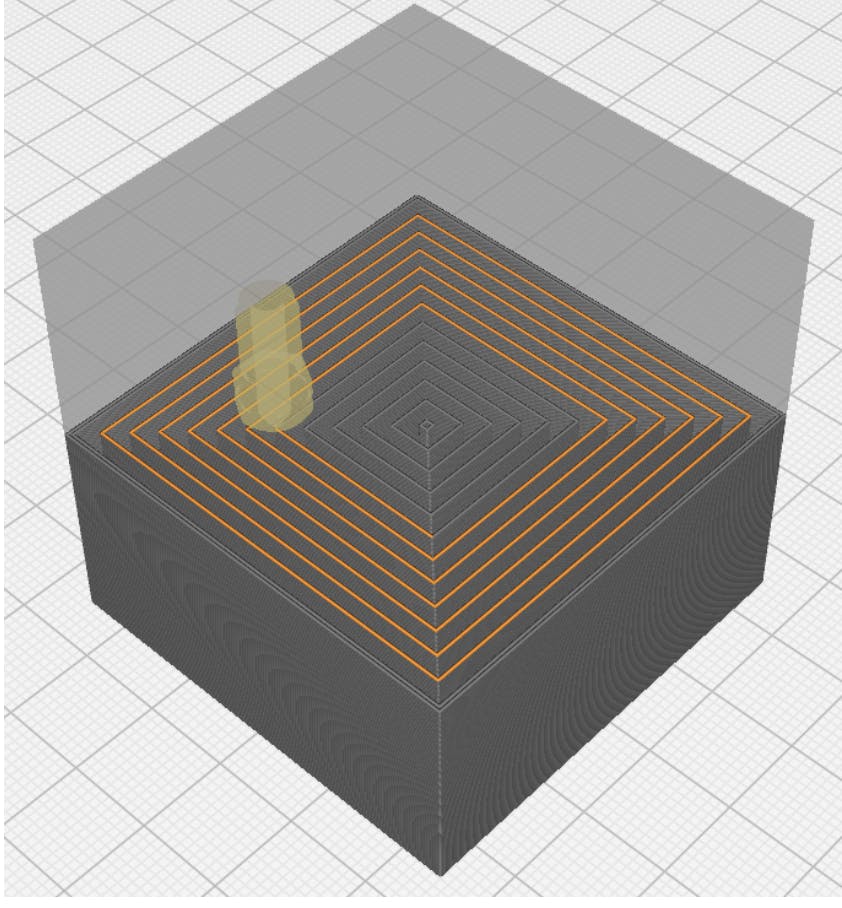
4. Concentric: The concentric 3D printing infill is one of the fastest infill patterns to print, and it uses the least material. However, this comes at the cost of reduced part strength. The concentric pattern is not as strong as the other infill types, especially when loaded in the x or y-directions. Figure 5 is an example of a concentric infill pattern:
Concentric infill.
Image Credit: Xometry.com
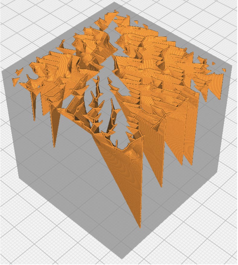
5. Lightning: This unique infill type provides the fastest possible print time at the expense of part strength. Supports are added in a lightning bolt structure and only placed where necessary. Parts are shells except where support is needed for horizontal features or internal overhangs. Figure 6 is an example of a lightning infill pattern:
Lightning infill.
Image Credit: Xometry.com
6. Triangular: The triangular 3D printing infill pattern lays down plastic in a triangular grid that crosses over itself at 60-degree angles. This type of infill pattern is best used on parts with large, flat surfaces, and performs similarly to the grid pattern. The triangular infill can cause the nozzle to clog, as its lines criss-cross each other in the same layer. Figure 7 is an example of a triangular infill pattern:
Triangular infill.
Image Credit: Xometry.com
7. Tri-Hexagon: The tri-hexagon is the strongest infill pattern. Like the grid and triangular infill types, it will cross over itself to create a hexagonal pattern interspersed with triangles. Due to the crossing of lines in the same layer, this type of infill tends to clog the print nozzle. Figure 8 is an example of a tri-hexagon infill pattern:
Tri-hexagon infill.
Image Credit: Xometry.com
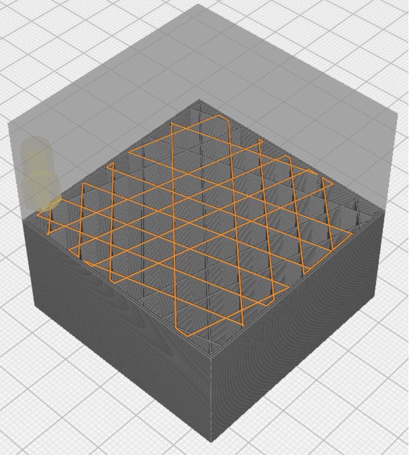
8. Cubic: The cubic infill type creates cubic volumes inside the part. It does this by producing a layered pattern similar to a triangular infill. However, it offsets each subsequent layer to build enclosed cube-shaped volumes in the part. The cubic volumes are oriented with the cube balanced on one corner. Figure 9 is an example of a cubic infill pattern:
Cubic infill.
Image Credit: Xometry.com
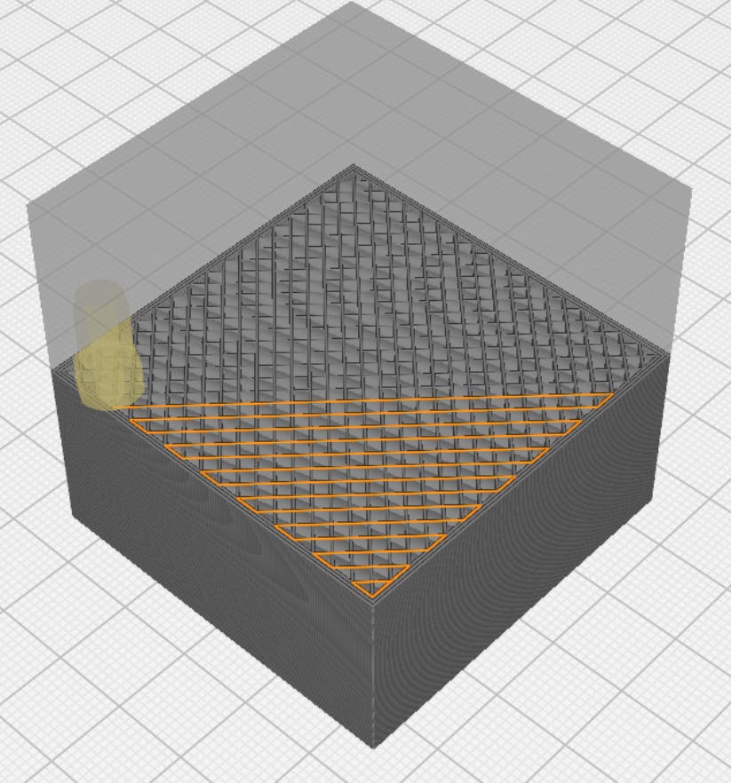
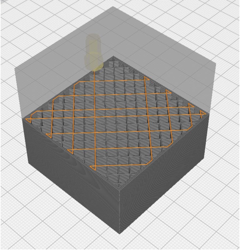
9. Grid: The grid is one of the most common infill types. The grid pattern lays down plastic in a cubic grid pattern that crosses over itself at 90-degree angles. This infill pattern is ideally used for prints with large, flat surfaces. Gridded infill patterns can cause nozzle clogging since the lines criss-cross over each other in the same layer. Figure 10 is an example of a grid infill pattern:
Grid infill.
Image Credit: Xometry.com
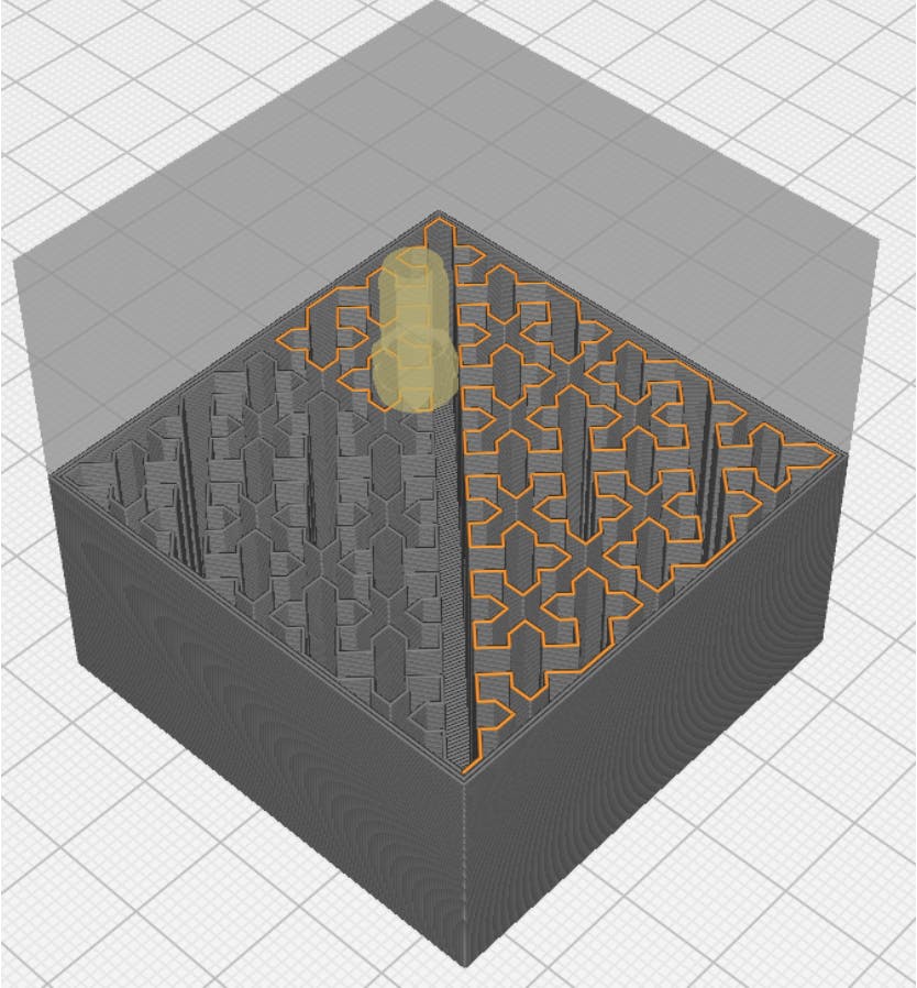
10. Cross: The cross pattern creates multiple cross shapes as infill. This 3D printing infill pattern is ideal for flexible part shapes as it allows for the part to bend and twist. It is not very useful for more rigid plastics, however. A 3D version of the cross is also available to add additional strength. Figure 11 is an example of a cross-infill pattern:
Cross infill.
Image Credit: Xometry.com
What Does the Ideal Value of the Infill Percentage Depend Upon?
The main determining factor for infill percentage is the type of application for which the part is destined to be used. Prototypes and hobbyist creations rarely need more than 20% infill. Functional parts that will be exposed to mechanical stress loads will typically require infill percentages of 50% or more.
What Is the Recommended Infill Percentage for Other Simple Exposure Objects?
For objects that will not see any significant mechanical load, a fill percentage of 20% is sufficient. It must be noted that the geometry of the part may require a different infill percentage. For example, a flat, horizontal surface may need a denser infill percentage to ensure that the top layer does not sag due to a lack of support.
How Much Infill Is Required To Achieve Maximum Tensile Strength?
The higher the infill percentage, the higher the tensile strength of the part. It must be noted that infill percentage is not the only factor that determines tensile strength. For example, filament material and print orientation play a major role. FDM parts, in particular, are anisotropic. They are weaker along the z-axis due to interlayer bonding weakness. If an FDM part is loaded in the z-direction, the dominant factor controlling its tensile strength will be the interlayer bonding quality. Infill percentage will have little effect in this case.
How To Choose the Best Type of Infill
The steps in choosing the best type of infill are:
- Check the part requirements. Calculate the infill percentage needed.
- Assess your resources, including the available material and the time you can spend per part.
- Shortlist the infill patterns that match your requirements and resources.
- Select the best infill pattern for your part.
Choosing the best infill pattern is often a trial and error process. It always pays off to do a trial print on a small part to figure out what the best settings are. Sticking with the simplest patterns, like a grid or line pattern, will normally yield good results.
What Is a Good Infill Density?
In most cases, an infill density between 20 and 50% is ideal. Less than 20% results in flimsy parts whereas more than 50% begin to take too much printing time and use too much material.
Is Infill Important for 3D Printing?
Yes, infill is an important consideration in 3D printing. Without infill, some parts may not be printable at all due to unsupported surfaces in the design. Infill adds extra strength where needed to strike a balance between the print time and the material requirements. Some parts can be printed without any infill. However, these are typically hollow shells with open tops (e.g., vases) and cannot be used for structural applications.
Summary
This article discussed the use of infill in 3D printing, the common types of infill patterns that exist, and how to select a pattern for use. To learn more about infill in 3D printing and how you can apply it to your products, contact a Xometry representative to discuss your project needs.
Xometry provides a wide range of manufacturing capabilities, including 3D printing and value-added services for all of your prototyping and production needs. Visit our website to learn more or to request a free, no-obligation quote.
Disclaimer
The content appearing on this webpage is for informational purposes only. Xometry makes no representation or warranty of any kind, be it expressed or implied, as to the accuracy, completeness, or validity of the information. Any performance parameters, geometric tolerances, specific design features, quality and types of materials, or processes should not be inferred to represent what will be delivered by third-party suppliers or manufacturers through Xometry’s network. Buyers seeking quotes for parts are responsible for defining the specific requirements for those parts. Please refer to our terms and conditions for more information.

