3D Printing is Not a Cheat Code
Get expert insight on understanding 3D Printing from our own Director of Applications Engineering, Greg Paulsen. Learn how to make the most of this additive manufacturing capability with his expert tips.

Engineers and designers are always interested in new technologies that can help them produce parts that fit their function. When a new technology arrives on the scene, there are often years of trial and error approaches as guiding principles are developed. Over time, certain manufacturing technologies have nearly dogmatic principles known as best practices. These practices are taught in academia and reinforced in real world applications.
For example, with CNC machining we typically look at internal holes using hole depth-to-diameter of no more than 8 without special tooling requirements. This means that a 0.25” hole really should not be more than 8X its diameter deep (2”). Even techniques like making corner radii a common size, and larger than the aforementioned hole ratio, will significantly reduce cost and increase the reproducibility of your part.
Similarly, for other tried-and-true manufacturing technology you see common rules that, when followed, significantly decrease the chances of your design needing modification for manufacturability. Injection mold has its draft angles and even wall thickness requirements. Sheet metal has guidelines for bend radius to material gauge of >1:1, as well as bending best practices like keeping the bends in one direction whenever possible or keeping a minimum distance from a hole feature to the bend.
With the onset of 3D printing, referred to as additive manufacturing, there has been a Wild West mentality of “shoot first, ask questions later” on printed parts. New users of the technology are sometimes surprised at the part’s surface, unexpected dimensions outside of tolerances, or critical features that are too fragile to function. This does not always lead to the desired outcome of the designer and can leave a bad impression of the technology.
Manufacturing paradigms
Current expectations for 3D printing do not reflect reality. The process does not build perfection and each additive technology has its own design rules. Most engineers who use additive manufacturing are approaching it with a rapid-prototyping mentality where a little tweaking is okay. However, communication gets lost in the quality supply chain when a 3D printed part that works gets adopted into production. Parts often get stopped at receiving inspection because their reference drawings have machining tolerances or slight deviations are noted between parts. This does not mean that the parts were built wrong, it means that the expectations and drawings were not designed for the process used.
Additive manufacturing requires a significant paradigm shift from conventional subtractive manufacturing, but once you start thinking about the process the designs can come much more naturally. This article will go over some guiding principles and a small handful of additive processes to better equip engineers to utilize 3D printing design best practices.
The first thing to understand is why additive manufacturing is more difficult to communicate versus traditional manufacturing approaches. Why is it that an engineer or quality manager can take a sheet metal, molded, or machined part and just push it through with ease? Simply put, the model is cut through subtractive methods—meaning that if there is a tight feature or tolerance, the machinist will review their program and shave down the feature to hit it as specified. So, the paradigm that most engineers and quality teams follow is:
- model made
- manufacturer interprets and programs digitally
- part (or tool) is milled
- part is delivered
What about additive 3D printing? To start, additive parts are grown from a lesser substance such as a powder, resin, or filament. This material is fused or cured to the shape of the model in a controlled manner. The model used is interpreted by the machine to output its best effort. So, the workflow is:
- direct digital manufacturing where a model is made
- the machine builds the part
- part is delivered
By this workflow, additive manufacturing should be interpreted more as a near-net shape than a built-to-spec process. The production teams who run additive manufacturing platforms only have so much control of machine parameters and focus on orientation optimization of the entire part versus discrete features. Instead of the machinist being responsible for the features of the part, it is in the engineer’s hands to design for the process. The 3D model used to print may have internal offsets and other features compensated for the process where a reference drawing would reflect the pass or fail criteria of the printed product.
This is easier said than done in some cases. With the current state of additive manufacturing all first prints should be revered as a prototype iteration. General guidelines will help build a better first article but more likely than not there will be several iterations before a stable, repeatable, and reliable model is finalized. Ultimately software will augment for this as machines get more sophisticated with data and feedback. But for the next few years at least these best practices will be very helpful to gain confidence in the process and manage expectations.
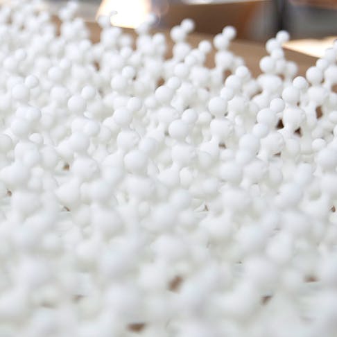
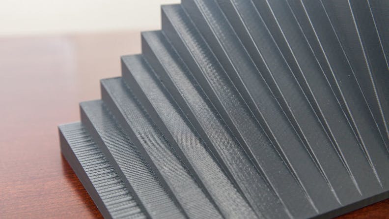
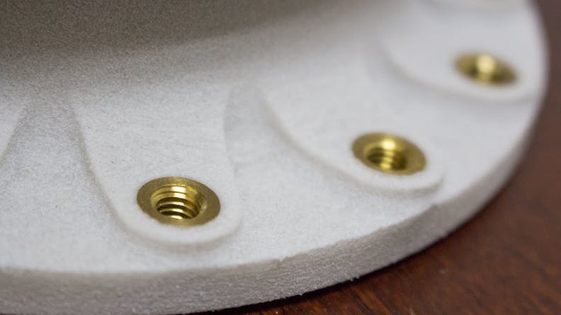
Additive manufactured parts are grown from the bottom-up versus cut down from stock, so their surface roughness depends the material used. For example, a selective laser sintered nylon piece is grown in a heated powder bed of nylon by a laser etching the cross section of a part before a new layer of material is deposited. As the laser fuses the powder the edges gain a slightly grainy texture, like a sugar cube. Other processes, like fused deposition modeling, use a heated filament to zig-zag back and forth building a part from bottom to the top. Because the base process is this filament you see more significant layer effects, especially on gradual curves where the layer-by-layer splits look like stair steps.
If a cosmetic face is the top requirement for the part as designed then additive manufacturing may not be the best fit. Getting an injection-mold-like surface finish takes significant manual finishing or machining. Some processes do have better finishes than others though. If a smooth matte finish is acceptable, UV-cured photopolymer processes like stereolithography, polyjet, HP multi-jet fusion, or Carbon DLS could be a great alternative. These materials are smoother because their base-material is a liquid resin which shows less layering than materials like thermoplastics. What additive can do well is create the shape of the part in some good engineering-grade materials.
A best practice for a designer working on a component in additive manufacturing would be to offset the CAD model to predict the outcome of the grown part. Depending on the process, features can be very dependent on other part characteristics. For example, in laser sintering you can see small gaps and holes close up. Sometimes standard sized holes are drilled open in post processing but “if the hole is irregular, or has a keyway, the general recommendation is to offset the interior surface by 0.006”. This means that a keyway will be 0.012” wider (0.006” per side) but when printed the hole will be near nominal. General tolerances can be applied as well. For example, here are some common process tolerances:
- Selective Laser Sintering (SLS): +/- 0.005” or +/- 0.002” per inch, whichever is greater.
- Fused Deposition Modeling (FDM): +/- 0.004” or +/- 0.002” per inch, whichever is greater.
- Polyjet: +/- 0.004”, or +/- 0.001” per inch, whichever is greater.
- Metal laser sintering (DMLS, SLM): +/- 0.001” - 0.006” is typical for positive features, and +/- 0.004” - 0.006” for negative features such as holes.
Build size in additive can also play a factor on quality. Growing to the maximum machine size can lead to warped parts. Thicker geometries, large broad parts, and parts with uneven wall thicknesses may deviate due to thermal shrinkage and stress. This can look like warping or twisting. Even wall thicknesses and similar design guidelines as injection molded parts are encouraged.
Some processes that are great for building large parts may have issues on smaller details. FDM works well for mechanical geometries, larger parts, and parts which may not require ultra-fine features. Very narrow pegs and lips may not resolve due to the bead thickness deposited. Minimum feature size, including text features, to be at least 0.035”.
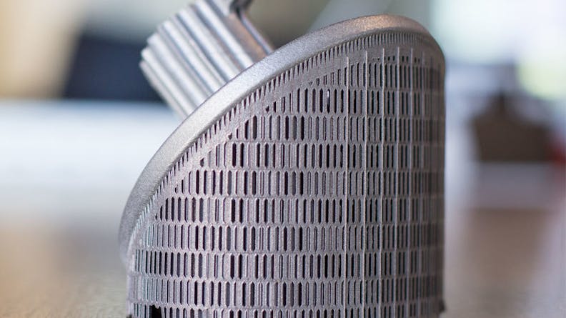
Some additive manufacturing processes, such as metal laser sintering, require support structures. These are disposable grown materials which are designed to hold an overhanging surface to a flat build plate. For metal parts, these could be fine metal tines or a solid mass of metal. Because these features are removed prior to delivering to the engineer they may have an inconsistent look to the rest of the piece. From a design standpoint, critical features should be designed in a way where they can grow with no or minimum support needs. This will give a much more predictable outcome to the print.
Orientation may play a role on strength of a part. For design considerations, small feature like pegs and clips should be planar, meaning they can all be oriented as close as possible to one direction. This allows the machine setup operator to orient the part so those features get the best orientation for strength. Features built horizontally will be stronger than features built vertically in most processes. Designing parts that will be vertical to a thicker cross section, or giving supporting ribs can also compensate for orientation differences.
So what is it good for?
Additive manufacturing is such an accessible technology with the ability to make parts that cannot be manufactured with traditional machining. It is also available right now for cost-effective, quicker-turn, prototypes and even on-demand production (with the right design considerations). With all the trade-offs there is still such a strong case for adding additive 3D printing to a designer’s manufacturing portfolio.
It only requires some trial and understanding from engineers and quality to communicate what is needed and how it can be done. Many 3D printing service providers offer a level of design-for-additive feedback or consultation and there are more options for printing coming out every year. In time, technology and education will catch up to additive just as it has for machining and molding. It is time to take this technology away from the hype and put it to work on your next project.


