Pick the Right Process for Small Features: The “Wicked-Small Cylinder Test”
At Xometry, we get a lot of questions about accuracy and feature size when it comes to our many 3D printing processes. So as a team we ran several benchmark tests over various platforms and recorded the results.

At Xometry, we get a lot of questions about accuracy and feature size when it comes to our many 3D printing processes. So as a team we ran several benchmark tests over various platforms and recorded the results.
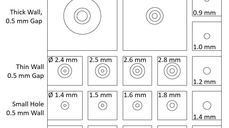
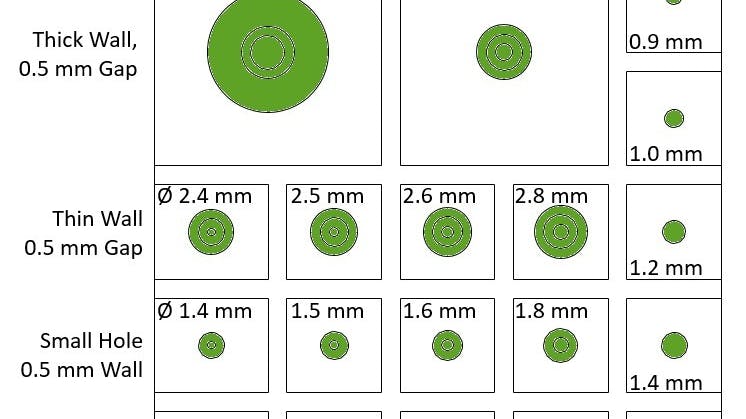
Where did we look for cool models to test our processes? Thingiverse, of course! There are a ton of great designs on this site and many benchmark models specifically to test 3D printers. Our first test was printing the “wicked-small cylinder test” made by the user leadingzer0 (http://www.thingiverse.com/thing:21945). This is a small 30 mm square with various cylinders of different diameters. Some of the cylinders have holes or gaps on the inside.
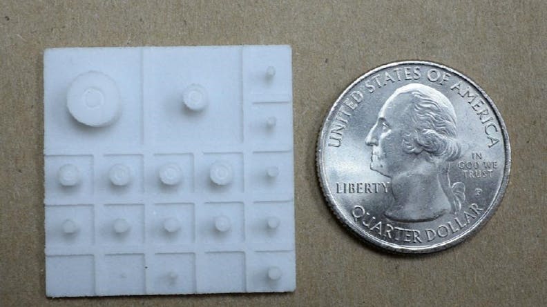
Xometry used our SLS, FDM, PolyJet, and DMLS processes to print this 3D CAD file and recorded the results!
For review, here’s a brief description of these processes
- SLS – Durable White Nylon fused by laser at 0.120 mm layers.
- FDM – Plastic filament deposited through an extruder nozzle at 0.254 mm layers
- PolyJet – Jetted resin cured by UV light at 0.030 mm layers
- DMLS – Metal powder fused by laser at; 0.045 mm layers
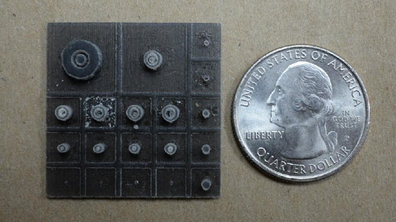
- Pegs: 0.6mm – 0.8mm visible but at risk of breaking during post-processing; > 0.9mm fully resolved
- Gaps ( 0.5mm): visible but partially filled-in due to over-sintering
- Holes: Fully resolved down to 0.4mm diameter
SLS Observations: What we found is that the SLS process will hit a laser where there is a feature on the part, but if the feature is too tiny (e.g. less than 0.5mm) you will get generalized results and irregular behavior. Similarly, small holes and gaps are usually fused shut or much tighter than designed – this is because the heat generated by the laser is being radiated between the walls of the holes and gaps and over-sintering the material.
SLS Conclusions: SLS is a really robust and “forgiving” process due to the toughness and flexibility of nylon; but for ultra-fine features, holes, and gaps you should consider compensating your model to the process versus getting fused geometry. An offset of 0.15mm can do wonders for slots – especially if they have mating parts. Usually, parts that are well designed for injection molding are well designed for Selective Laser Sintering.
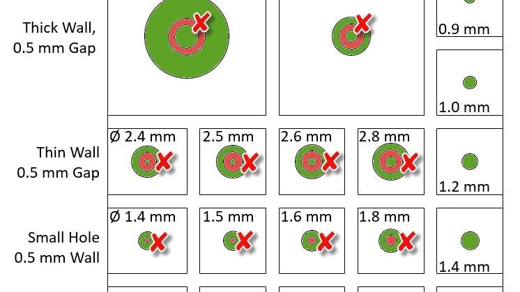
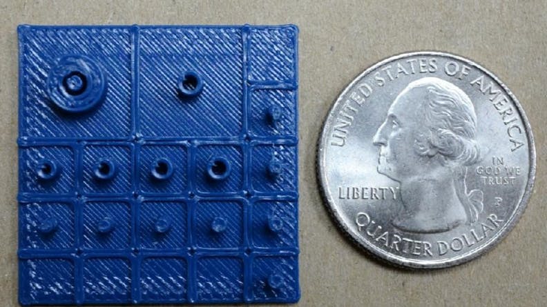
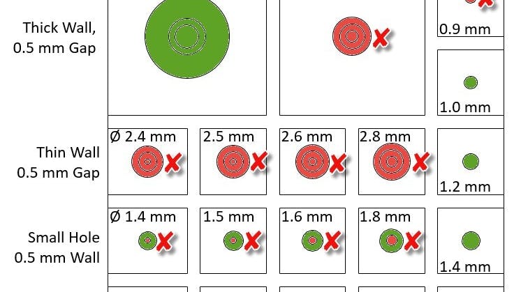
- Pegs: <1mm did not resolve
- Gaps (0.5mm): Resolved in features where peg >1mm
- Holes: <1mm did not resolve
FDM Observations: Due to a fixed filament width any small features that are not self supporting and less than two filaments thick (~0.7-0.9mm) will not even be programmed in the XY direction. This means that all the test pegs from 0.4 to 0.8mm literally did not show up in the machine code because there was no way to deposit filament successfully with our standard layer thickness of 0.254mm (0.010” layers). The fixed filament width also means that smaller cylinders may be filled. We also noted that since the cylinders are being grown vertically there is not a lot of strength in the XZ direction and the small columns can be easily broken.
FDM Conclusions: Fused Deposition Modeling is very mechanically accurate, has a huge variety of engineering-grade plastics, and offers our largest build volume but small feature details may not be its strong suit. When designing for the process you should be considering how the part will be oriented – generally with the lowest Z direction unless there are many concentric / repeating features which may have a better alignment. Snap tabs and small pegs suffer and break easily with FDM so please think of reinforcing those pieces or making replaceable joining features so a broken tab does not ruin an otherwise perfect part.
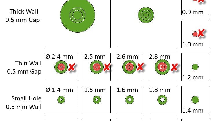
- Pegs: < 1.2mm in diameter are at risk of damage during post-processing
- Gaps: </= 1mm are at risk of not allowing support material to be removed
- Holes: </= 1mm are at risk of not allowing support material to be removed
PolyJet Observations: PolyJet was able to resolve features down to 0.5mm, but pegs less than 1mm were damaged during support structure removal. Gaps and holes were fully resolved, but clearing them out also risked damage to adjacent features.
PolyJet Conclusions: With the highest Z-height resolution of any of our 3D Printing Processes (0.03mm), PolyJet can print some very small features. As a UV cured photopolymer, thin features tend to be more rigid and less robust than those printed in SLS and FDM. This is shown in the broken pegs smaller than 1mm. With its higher resolution and semi-gloss finish PolyJet parts are often ideal for models to be shown during presentations or tradeshows, but not necessarily end-use parts. One large benefit of PolyJet is our short lead time. We typically ship in one to three business days.
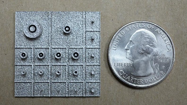
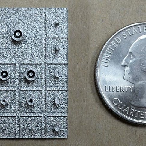
- Pegs: Fully resolved > 0.4mm dia
- Gaps (0.5mm): Fully resolved
- Holes: Fully resolved down to 0.4mm dia
DMLS Observations: Pegs and holes larger than 0.4mm printed successfully as did all of the 0.5mm gaps. Features are crisp and there appears to be very minimal over-sintering.
DMLS Conclusions: Comparing all the test coupons shows that small features were are most accurately resolved in DMLS Stainless Steel. With a .04mm Layer height, DMLS is able to resolve some really small features. Additionally, the strength of the fused metal makes small details extremely robust.
Please feel free to reach out to our project engineering team if we can assist further! We also have more information regarding tolerances available here!

