Video: Will It Fit?
Watch our new video for best practices on designing for mates in CNC machining versus 3D printing.

In our latest video, Director of Applications Engineering, Greg Paulsen, compares machined and printed parts to see how they mate and shares best practices for designing your custom parts.
How will the machined parts mate compared to various additive processes? Watch and find out!
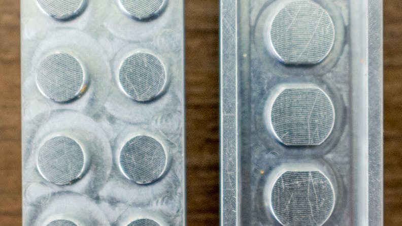
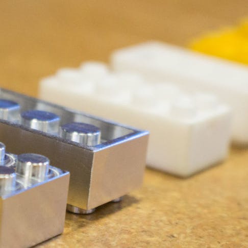
CNC machined test part for Will It Fit test
CNC Machining
We started with a CNC design with critical dimensions designed to nominals, tight tolerances called out in critical areas, and an accompanying drawing to ensure the parts would work as designed. We also made the interior cavity much more shallow, added radii on internal corners, and removed the hollow from the center columns. In order to keep the tool size consistent, the internal columns had a minimum clearance channel between the features.
How did it work? Maybe aluminum was not the best choice for this because it was unforgiving on mates. We milled for a light interference fit and were able to achieve that. We did notice that even a slight change of thousandths could lead to a really tight fit requiring a vise to pull the pieces apart! In the opposite direction, the part would act loose.
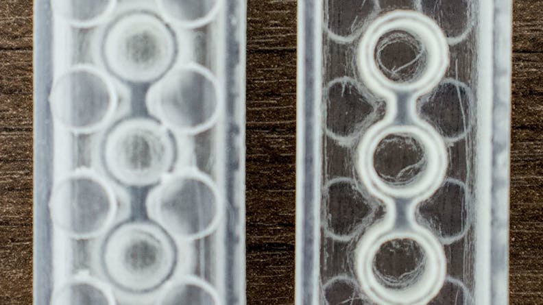
PolyJet test part for Will It Fit test
PolyJet 3D Printing
PolyJet, our most accurate process, required minimal tweaks. The biggest concern was the three internal columns. Because we clean PolyJet out with a high powered water jet, the internal columns were vulnerable. We reinforced the columns with a center rib and added heavy fillets in the bottom to ensure the part would not break during post processing.
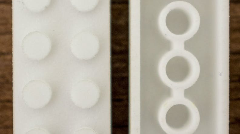
SLS test parts for Will It Fit test
SLS 3D Printing
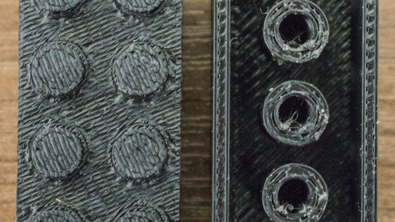
SLS, our most versatile process, required some more process-specific predictions. We know that internal gaps close and thin walls thicken so we added 0.006” clearance offset in the internal cavity. As with PolyJet, we added internal walls and fillets to help strengthen the inside columns. We also added a clearance channel since we clean the parts with bead blasting. The small holes at the bottom of the boss on the outside of the piece allow the beads to channel out of the part without building up. We ended up doing two revisions of the SLS piece because we initially gave a 0.004” inwards offset on the pegs and found it too loose. We adjusted to 0.002” and that seemed just right.
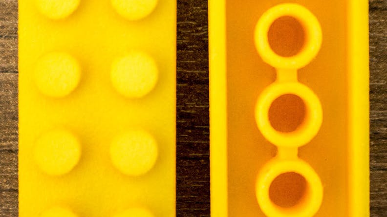
FDM test part yellow for Will It Fit test
What Did We Find?
3D Printing can lead to repeatable and predictable results, but we always look at the first print as a trial attempt when designing. It’s okay if the first piece does not work because additive process are relatively inexpensive compared to CNC and have significantly shorter lead times. You can also do multiple attempts at once using the “shotgun approach” to see which offsets work best in the process. Another recommendation is to test out only critical features if you have a large piece to print. It will save time and a few headaches!
CNC Machining is a precise process and requires understanding of design as well as tolerances to get the most out of it. If this design was made with standard tolerance, the results may have been an incompatible fit—it’s important to dictate the intent of the design using a well-constrained drawing. In general, adding proper clearances, internal radii, and tightly tolerancing only the necessary features will drive costs down and reproducibility up.
Don’t forget to check out our other 3D Printing challenges:

