Rapid Injection Molding: Definition, Components, and Materials
Learn more about the rapid injection molding process and how it's used in manufacturing today.

Rapid injection molding (RIM) is an injection molding process designed for the manufacture of relatively small batches of plastic parts with much shorter lead times than the standard injection molding process. In general, the equipment used for RIM is the same as that used for normal production injection molding except that RIM injection molds are designed for quick turnaround instead of for long series production durability
The gain in concept-to-production lead time comes primarily from using mold materials like aluminum, which are less expensive and easier to machine than standard injection mold materials. The molds will not have the durability required for long series production runs, but they are good enough for smaller runs of at least 500 parts.
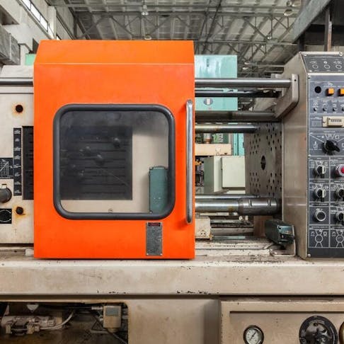
This article will describe the rapid injection molding process, explain how it works, discuss the equipment used, and offer some tips on how to choose the optimal part material. A typical injection molding machine is shown in Figure 1 below:
An injection molding machine.
Image Credit: Shutterstock.com/Moreno Soppelsa
What is Rapid Injection Molding?
Rapid injection molding makes use of normal injection molding equipment and techniques but does so at a much shorter lead time and at a reduced cost. This short lead time is desirable for custom prototypes and manufacturing limited volume production runs to iron out any potential design issues before committing to full production-scale injection molding. This speed is mainly due to the use of cheaper molds and easy-to-machine materials like aluminum that can be manufactured in just a few weeks. Rapid injection molding must not be confused with reaction injection molding which refers to the process of injection molding a thermosetting plastic.
For more information, see our guide on Plastic Injection Molding.
Where is Rapid Injection Molding Being Used?
Rapid injection molding is primarily used for prototyping, research, and developmental applications that do not require hundreds of thousands or even millions of parts. RIM is best suited to production runs with volumes of at least 500. This allows engineers to test their designs with limited capital investment instead of immediately committing to the very expensive, long lead time tooling needed for high-volume series production. Production injection molds cost so much partly because they must be made from highly wear-resistant materials to ensure that they can withstand the rigors of long-term production use. For that reason, RIM is often used to bridge the gap between initial design and full-scale production and is a cost-effective way to test new products, materials, and design tools. RIM can also be used to manage sharp increases in product demand volume.
How Does Rapid Injection Molding Work?
Rapid Injection Molding (RIM) parts must be designed with DFM (Design for Manufacturing) principles for injection molding in mind. A RIM mold is specifically created to be inexpensive and quick to manufacture, using standard, off-the-shelf materials. Aluminum molds are typically used as they are easier and faster to machine but are not able to handle high-volume production.
Once the specialized RIM mold is manufactured, its two halves (core and cavity) can be mounted onto the stationary and moving plates of a normal injection molding machine setup, because the rest of the molding process is the same for both RIM and standard injection molding. The halves of the mold are brought together and held in place with hydraulic rams.
To actually make parts using the RIM process, the raw material (typically thermoplastics and thermoset silicones) is fed into a screw housed in a cylinder called a barrel. A combination of heat provided by external heaters mounted on the barrel and heat produced by shear (or frictional) forces between the plastic pellets and the action of the screw in the barrel, melts the plastic pellets. Once enough plastic has been melted, the screw pushes this plastic into the mold through a nozzle and a one-way valve on the screw stops pressure from receding back into the screw. High-pressure plastic then fills the mold, and the hydraulic rams ensure that the plastic does not ooze out at the split line between the mold halves. After a few seconds, the plastic solidifies and the mold opens. The part is ejected using ejector pins, the screw retracts, and the process repeats. It must be noted that rapid injection molding does not produce individual parts any faster than standard injection molding.
Where is the Equipment for Rapid Injection Molding Typically Made?
The equipment for rapid injection molding is typically made by injection molding machine manufacturers. Manufacturers are typically situated in China, Europe, and the United States. Note that the only difference in terms of equipment between rapid injection molding and standard injection molding is the mold. These molds are made by injection molding tool makers.
What Are the Components of a RIM Press?
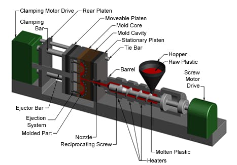
The components used in a rapid injection molding (RIM) press are described in detail below. The main components are the same parts that are used in a standard injection molding press. The various parts of an injection molding machine are labeled in Figure 2 below:
A diagram of parts of an injection molding machine.
Image Credit: injectionmouldingworld.com
1. Hopper
The hopper is where the thermoplastic resin pellets are placed for dispensing. The hopper is normally fed from bulk bags or a silo, depending on the required production volume and part size. This hopper provides a continuous supply of material to the screw. In some cases, it also preheats the resin so that it can be melted more rapidly in the screw and barrel. This reduces the per-part production cycle time. The hopper may also have level sensors to warn operators that they need to top up the material in the hopper.
2. Screw
The reciprocating screw has multiple functions. First, it meters and transports the correct amount of material from the hopper into the mold. While transporting the raw material, it rotates, forcing the pellets into an ever-decreasing volume which is created by the screw shaft increasing in diameter. This creates enough heat to melt the pellets via the shear force created by the plastic pellets shearing against the screw and the barrel. Some screws also mix the material to create a more homogeneous melt and in some cases to ensure evenly mixed additives. Once enough material has been melted, the screw rams forwards and a one-way valve on the end of the screw ensures that the material cannot move back down the screw and is rather forced into the mold. The screw then retracts and the process is repeated.
3. Barrel
The barrel houses the screw and is designed to guide the raw material into the mold. The barrel typically has heating elements wrapped around it to assist in melting the pellets. The screw forces the plastic pellets against the barrel and causes an increase in friction which melts the plastic. The injection nozzle is located at the end of the barrel.
4. Heaters
The barrel has a number of electrical heaters wrapped around it to aid in heating up the plastic pellets. It must be noted that these heating elements are not the primary heat source for melting the plastic. The pressure induced by the screw forcing the pellets against the inside of the barrel creates shear heating that melts the plastic.
5. Materials
The materials used in rapid injection molding are thermoplastics. These materials can either be a commodity or specialty depending on the desired end-use.
6. Nozzle
The nozzle directs the injected plastic into the mold. It may have a diameter of anywhere from 2.5 to 10 mm depending on the capacity of the injection molding machine. The nozzle is screwed directly onto the barrel. Nozzles may have filters to prevent unwanted particles from entering the mold. There are two different filter styles: screen pack and gap filters. Screen pack filters are not popular, as they impede the flow through the nozzle, creating pressure loss whereas gap filters provide a larger filter area and do not impede the flow as much. Nozzles can also have a mixing function that creates a homogeneous melt and helps in dispersing additives like colorants more evenly throughout the melt.
7. Mold
The mold is typically made from two parts: the core and the cavity. The different parts of the mold are each mounted to a plate called a platen. One mold half is held stationary while the other half is pressed against it with a hydraulic ram. This ram applies enough pressure to ensure that the plastic does not exit the mold at the parting line. Molds often have cooling channels machined into them to allow for a heat transfer fluid to remove heat from the mold. These cooling channels help the part solidify quicker and reduce the overall cycle time. Once the part solidifies, the molds open and a set of ejector pins push the part from the mold. The mold closes and the cycle repeats.
RIM molds are made using cheaper and easier-to-machine materials and are designed to only last for at least a few hundred parts. Another method used to reduce cost and increase production speed in RIM is to make use of master unit dies (MUD), which allow for modular molds that enable quick implementation of design changes without having to remanufacture an entire mold from scratch.
8. Part
The part is the end result of the injection molding process. Injection molded parts must be designed with injection molding design for manufacturing principles in mind in order to achieve high-quality parts. These rules determine the optimal wall thickness, where to add reinforcing ribs, hole sizes, etc.
What is the Wall Thickness of Rapid Injection Molded Parts?
The wall thickness of a rapid injection molded part is typically between 1.5 and 2.5 mm. However, this thickness also depends on the material being used as different materials have different ranges for optimal wall thickness. There is no difference between the wall thicknesses common with normal injection molding and what is possible with RIM.
How to Choose the Best Materials for Rapid Injection Molding
Choosing the best material for RIM depends on the desired end use of the product. RIM is used for prototype, pilot, and short-run volumes, bridging the gap between design and full-scale production. Thus, the materials used must be the same as those intended for full-scale production. One key advantage of RIM is that multiple materials can be tested to determine which is optimal. Some key considerations when deciding on the best material are cost, mechanical strength, UV resistance, electrical properties, and thermal resistance. These properties can be enhanced with the inclusion of additives like glass or carbon fibers, it must be noted that these types of fibers are very abrasive and reduce the overall life of the mold which is especially true for aluminum molds.
What Materials Are Used for Rapid Injection Molding?
Rapid injection molding makes use of commodity thermoplastics like polypropylene and polyethylene, as well as specialty materials like nylon and polycarbonate.
What Are the Benefits of Using Rapid Injection Molding?
The key benefits of using rapid injection molding are: reduced lead time, increased design flexibility, and multi-material testing. Low-volume production runs can also be implemented for on-demand manufacturing.
Is Rapid Injection Molding Quick?
Yes, rapid injection molding is quick. Lead time from design submission to obtaining sample parts is much faster than the typical lead time for full-scale production injection molds.
Summary
This article presented rapid injection molding, explained what it is, and discussed different parts of an RIM press. To learn more about rapid injection molding, contact a Xometry representative.
Xometry provides a wide range of manufacturing capabilities, including injection molding and other value-added services for all of your prototyping and production needs. Visit our website to learn more or to request a free, no-obligation quote.
Disclaimer
The content appearing on this webpage is for informational purposes only. Xometry makes no representation or warranty of any kind, be it expressed or implied, as to the accuracy, completeness, or validity of the information. Any performance parameters, geometric tolerances, specific design features, quality and types of materials, or processes should not be inferred to represent what will be delivered by third-party suppliers or manufacturers through Xometry’s network. Buyers seeking quotes for parts are responsible for defining the specific requirements for those parts. Please refer to our terms and conditions for more information.


