How to Choose Core and Cavity Placement in Injection Molding
Our guide to understanding the best practices to follow in injection mold design.

A mold is the heart and soul of the injection molding process—not only is it one of the most time-consuming and expensive aspects of injection molding, but the success of every product that goes through the injection molding machine depends on it. Injection molding experts well know the importance of mold design; however, it can be far from easy to determine precisely how to design it correctly.
This article will help by briefly exploring how to choose core and cavity placement in injection molding, first by looking at the basics of injection molding, then working through various considerations for injection molded parts.
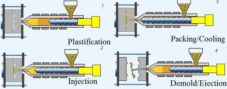
Cycle of conventional injection molding process.
Injection Molding Process/ResearchGate.Net
The primary injection molding cycle steps are as follows:
- Plastification: Plastic granules are fed into the machine’s hopper, where the reciprocating screw draws back, allowing materials to slip into the space between the screw and the barrel. The screw forces the material through the heater bands, where it melts.
- Injection: The screw forces the material further into the mold cavity (made up of two clamped mold halves), where it fills the void space and pushes out any trapped air through the mold vents. Once the plastic has filled the entire mold cavity, including its sprues, runners, gates, etc., pressure is applied to distribute the melted plastic through the mold (called the holding pressure).
- Packing/Cooling: The mold is kept at a set temperature to uniformly solidify into the part shape and evenly distribute through the cavity space. The holding pressure is maintained while cooling, and when cooled, the part is ready for the final step.
- Demold/Ejection: The mold halves separate, exposing the finished and cooled part (where the part is stuck to only one mold half). The ejector pins eject the part from the mold half it is attached to, releasing it into a receptacle.
These four basic steps illustrate how plastic enters the mold through only one of its halves, and how the mold is constantly opened/closed during cycles. Designers must ensure that the finished part always sticks to the same side of the mold when ejecting, as only one half can house the ejection system (and can therefore release the part). It is also essential that no space be left unfilled and that these spaces fill and cool evenly. Otherwise, it leads to costly defects.
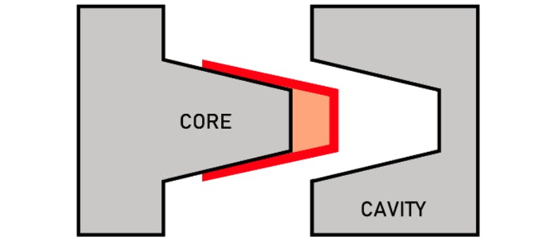
The core and cavity shown in two mold halves.
Core and Cavity/Christian Cavallo Consulting LLC
The closed volume of the mold cavity is created using (at minimum) two mold halves. In two-part tool molds, these halves are either cores or cavities.
The core is the side of the tool mold that contains the interior or non-cosmetic side of the part. The core is also where (in most configurations) the ejector system is located. In the above visual, the inside of the cup is the non-cosmetic side, and so the core forms the inside of the cup.
The cavity is the side of the tool mold that forms the exterior or cosmetic side of the part. It is often polished to a finish that represents the desired final surface finish of the part.
When placed together, the core and cavity will leave a thin-walled cavity that will eventually be filled with melted plastic and allowed to cool.
What Affects Core and Cavity Placement?
It is vital to determine the best arrangement of mold components; otherwise, the injection molded part will fail. The above image intentionally removes many parts of a mold to highlight the core and cavity but note that there are several components and concepts that will affect the core/cavity placement (and the success of the project).
Below is a brief list of what affects core and cavity placement:
- Part shape: the above image shows a simple, cylindrical shape, but many injection molded parts are highly complex. The part shape will not only determine where to place the core and cavity in the mold but also where ejector pins, cooling channels, and other necessary components go (which in turn affect core and cavity placement, etc.). Also, uniform wall thickness is a priority in part shape, as variable wall thicknesses will cause issues in both cooling and ejection.
- Ejector System: When the mold is opened after the cooling stage, the injection molded part must ALWAYS be stuck to the side of the mold with the ejector pins. The ejector system and its specific shapes will affect where the core and cavity are placed, such that consistent, repeatable ejection is achieved.
- Material: The shrink rate, flow characteristics, and injection speed of the material will partially dictate how the core and cavity are arranged. If a material has a low shrink rate, it will be more challenging to get the part to stick to the ejector pin side, therefore calling for design considerations. Luckily most plastics do shrink considerably, but it is important to understand how the material could potentially affect where the core and cavity should go.
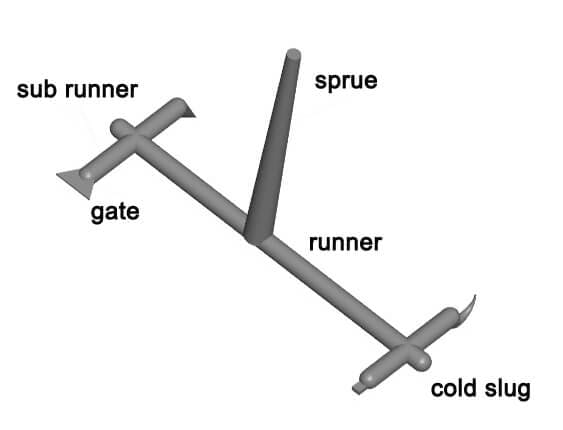
- Gates, Runners, and Sprues: The sprue is the primary channel from the injection molding nozzle that feeds plastic into the mold cavity. It is typically perpendicular to the mold cavity’s axis but can sometimes be directly piped into the cavity (in that instance, the sprue is known as a direct sprue gate). Runners are the channels that feed multiple mold cavities with molten plastic from the sprue. Most injection molds use runners as it is more economical to mold multiple parts in one cycle (especially in the case of small parts such as model kit parts, for example). Gates are the entry points from the runner into the core and cavity and are typically much narrower than the runner.
Each of these components affects core and cavity placement and must be smartly designed. The sprue and runner locations must be placed in such a way that allows for sufficient filling of all features of a part. Proper gate location affects core and cavity placement, as they influence how the core and cavity fill and how the part will look aesthetically, as it is the point at which the part is cut off from the runner system (assuming a cold runner design).
The image below illustrates the plastic mold feed system typically employed with plastic injection molding.
Plastic mold feed system including sub runner, sprue, gate, runner, and cold slug.
Plastic mold feed system/PlasticMould.Net
Core and Cavity Placement Considerations
Below are some useful tips when considering how to arrange the core and cavity placement in an injection molded part. Note that this section is nowhere near exhaustive, and qualified design engineers, mold technicians, and injection molding professionals should be consulted when regarding the core and cavity placement of a specific project.
Xometry can assist with questions on mold design - contact us for assistance as needed.
Core and Cavity Design
There are some key rules when designing injection molding cavities that will reduce defects and increase the chances of clean ejection from the mold, for example:
- Including rounded corners/edges
- Adding ribs for supports
- Adding bosses for threaded inserts
- Avoiding vertical walls (i.e. walls perpendicular to the parting line of the mold)
- Using uniform wall thickness as much as possible
- Creating hollow cavities in thick sections
etc.
These rules impact the placement of the core and cavity in an injection molded part, as they limit where and in what orientation these features can be. For example, ribs or bosses must not be arranged vertically, otherwise, there is a risk of the part getting caught in the mold. Understanding how the material will fill the core and cavity will help determine how it should be oriented and inform mold design.
Draft Angles
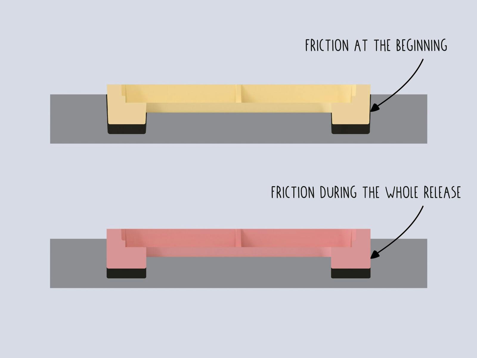
The draft angle, or the calculated angle of walls to the vertical axis of the mold to account for thermoplastic shrinkage, is an especially important aspect of core and cavity design. See the diagram below for an illustration of this concept.
Checking surfaces for draft angle.
Draft angle/OneArmy.GitHub.io
Plastic that is perfectly vertical in a mold design (especially around a core or inside a cavity) will experience friction and suction as it tries to release from the mold. Proper draft angles (shown above in the image) reduce the friction and release the vacuum by providing space in the design. Draft angles are also used to keep the part on the proper side of the mold with strategic placement of the core and cavity.
Machining Considerations
Injection molding molds must be fabricated; creating a perfect design that is perfectly impossible to machine is, well, imperfect. Place the core and cavity to reduce unnecessary milling, cutting, tapping, or other procedures, which allows for a good surface finish. Mold designers often use CAD software to play out each machining procedure needed step-by-step to achieve the specific features of a given mold. Such software includes Autodesk Fusion, Solidworks, ZW3D, and others.
Filling, Thermals, and Shrinkage
Material characteristics such as flow rate, heating & cooling temperatures, and shrinkage rate will influence the core and cavity placement, so it is essential to consider all of these when designing a mold. There is injection molding simulation software that helps predict how a given design will function by simulating shrinkage, temperatures across a cycle, and how evenly cores and cavities fill through a given runner system. Employing one of these software packages will help find the best placement of cores and cavities and will also provide design suggestions to iterate on, such as places for more uniform wall thickness, rounded edges, etc. (instead of actually making a mold, trying it, and then going back to the drawing board when it fails). Popular injection molding software for this purpose is Autodesk Moldflow, Moldex3D, SOLIDWORKS Plastics, and many more.
Summary
This article presented how to choose core and cavity placement in injection molding.
Xometry offers a full range of injection molding capabilities to help with your production needs. Visit our website to explore the full range of our capabilities or to request a free, no-obligation quote.
Disclaimer:
The content appearing on this webpage is for informational purposes only. Xometry makes no representation or warranty of any kind, be it expressed or implied, as to the accuracy, completeness, or validity of the information. Any performance parameters, geometric tolerances, specific design features, quality and types of materials, or processes should not be inferred to represent what will be delivered by third-party suppliers or manufacturers through Xometry’s network. Buyers seeking quotes for parts are responsible for defining the specific requirements for those parts. Please refer to our terms and conditions for more information.

