Top Design Tips for Laser Tube Cutting
Our top tips for optimizing and improving your laser tube cut part designs.

Xometry offers an extensive range of laser tube cutting services on metal and non-metal materials, allowing precision cut shapes, holes, designs, and channels using a CNC laser. The laser is tuned to pierce the tube while not damaging the opposite wall, allowing maximum design freedom and asymmetrical features. Many tube laser cutting platforms can also angle the laser for beveled cuts, countersinks, and angled joints ready for welding. Tube laser cutting is often the preparatory process for other operations such as tube bending, which we also offer. The versatility of laser cutting technology allows designers to create more complex tube parts faster than ever. That said, it pays off to develop your designs thoughtfully. A thought-out design will increase productivity, lower risk, and in turn, result in lower costs.
This article will cover our top design tips and considerations so you can achieve the optimal design for your laser tube cut parts. The topics we will cover include:
- Hole Size
- Tabs, Slots, and Joints
- Dimensioning
- Weld Seams
- Normalized Cuts
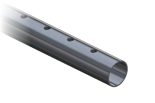
Holes in a laser cut tube part.
Minimum Hole Size
The most critical consideration when designing holes in laser-cut tube parts is the tube’s wall thickness. In combination with material thickness, the laser beam size or pierce point dictates the minimum recommended hole size. The thicker the material is, the larger the hole diameters must be to ensure the laser can perform a precise cut. Holes smaller in diameter than the material is thick are more likely to be out of tolerance.
Pro Tip: Keep hole diameters equal to or greater than the tube wall thickness.
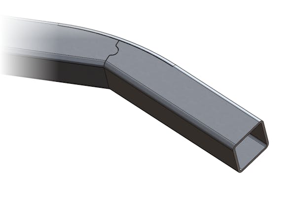
Laser cut joint in a bent tube.
Optimize Assemblies with Tabs, Slots, and Joints
By utilizing laser-cut tabs, slots, and joints in your parts, you can simplify your assemblies and, in some cases, eliminate secondary processes. Tabs with corresponding slots on mating parts enable you to quickly form joints between parts and help reduce complex welding jigs. As shown in the image above, large frames can be constructed and bent manually from a single tube by designing joints with relief cuts and indexing features.
Pro Tip: Make sure you design enough clearance to account for the laser’s kerf and possible cut taper, especially with thicker walled tubing. Normalizing cuts will help avoid joint fit-up issues and reduce trial and error with test cuts.
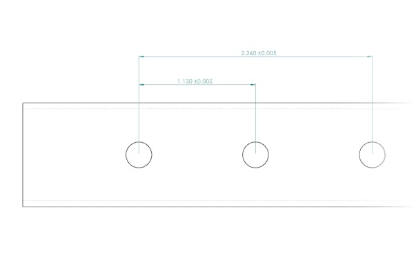
Diagram of hole to hole dimensions on a laser tube cut part.
Dimensioning and Tolerances
When working with tube materials, a crucial consideration is the stock material tolerances. Tube material tolerances tend to be larger than sheet or plate stock. Also, consider that the larger the diameters of the material become, so do the stock tolerances. When tolerancing features, try to avoid hole and feature to feature tolerances tighter than ±0.003”. Overly tight feature tolerances may require secondary operations such as post-machining, which can significantly increase cost and lead time. The outside edges of tubing tend to be less precisely cut; therefore, you should avoid dimensioning features from the outer edges. You can find tube cutting general tolerances in Xometry’s Manufacturing Standards.
Pro Tip: Avoid dimensioning from outside edges and reference critical features from the tube centerline.
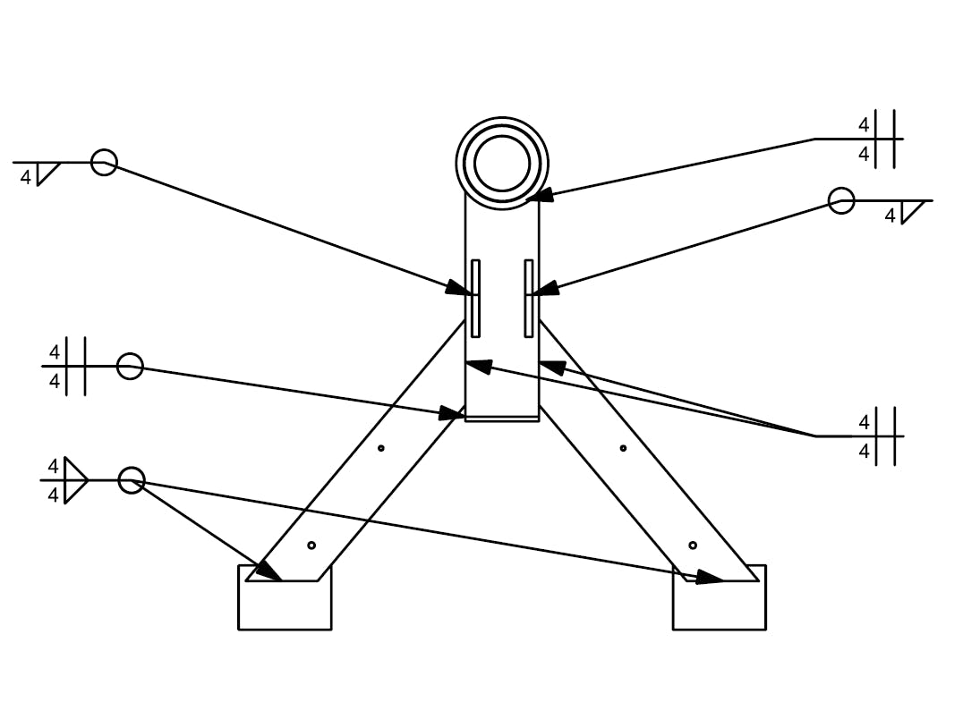
Diagram of a tube weldment with various weld seams.
Weld Seams
Welded tubes, pipes, and other profiles are a great way to reduce material cost; however, a prominent weld seam may be present in the material. Considering the weld seam location is essential to prevent interference with mating parts and to cut critical features. In some instances, the added thickness of the seam in the material can cause cutting difficulties that can make it challenging to precisely cut features and hold tolerances. Using appropriate welding symbols PER ANSI/AWS A2.4, Symbols for Welding and Nondestructive Testing, on your technical drawing is the best way to communicate your design intentions with a manufacturer. The image above depicts a multi-part weldment with fillet (V-like call out) and square groove (H-like call out) welds.
Pro Tip: Design around seams on welded material and call out the location on your drawing so the manufacturer can orientate the tube accordingly during production. Request seamless tube joining when welded material is not permissible, although it will typically come with a higher cost.
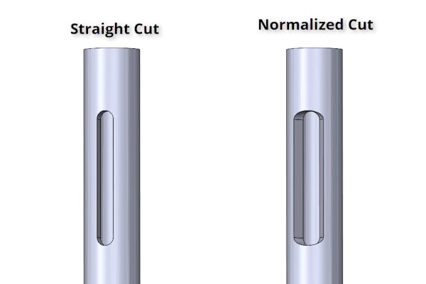
Part with straight cut slot (left) vs. normalized cut slot (right).
Normalizing Cuts
Although many of our partners utilize sophisticated laser tube cutting machines with multi-axis heads, normalizing the cuts on your part will increase its manufacturability and often reduce costs. Normalized cuts allow the laser head to remain at a 90-degree angle to the cutting surface at all times, so it does not need to slow down for tilted cuts. In addition, it prevents cutting difficulty and excessive heat build-up caused when attempting to make sharp cuts in material with thick walls. Generally, tube-cutting lasers operate most efficiently when the laser is cutting towards the center of the tube.
Pro Tip: In addition to increased manufacturability, designs with normalized cuts will help mitigate trial and error with test cutting, enabling you to refine and achieve your final design more quickly.


